Installation

Notes

There is no absolute position required for system installation, as long as all the prompts in the installation guide are followed to ensure the system can function properly.

If you have any questions about the following content, you can seek advice from a professional vehicle maintenance personnel, or contact us before installation to clarify your doubts before proceeding with the installation.

If you are unable to install it yourself, please pay the necessary installation fees and have it installed by a professional.
Work Overview

  1. Download the XThruster® app to your phone to complete the control program installation.
  2. Find a suitable location for the controller to trigger vibration (the installation location must be able to receive engine vibrations).
  3. Make sure the vehicle is turned off.
  4. Find the location to connect the device tubing to the vehicle’s intake system, which can be on the air filter housing or on the intake tube.
  5. Find the installation location for the controller and reaction tank, and ensure that the distance between the two is sufficient for the control wiring to connect and the controller to receive power supply. The reaction tank tubing should also be of the optimal length to connect to the intake system.
  6. The reaction tank is fixed first and the pipe is installed.
  7. When selecting the installation location for the controller, pay attention to the directionality of the Bluetooth antenna. Improper placement or the presence of metal or glass insulation paper can affect the connection between the controller and the phone inside the car.
  8. Secure the controller and connect the cables between the controller and the reaction tank.
  9. Connect the controller to the positive and negative power supply via the accompanying 7A fuse.
  10. Check that all installation steps are complete.
  11. Refill the reaction tank with catalyst according to the catalyst adding instructions.
  12. Start the engine.
  13. Use XThruster® app connect to the controller via Bluetooth.
  14. Set the parameter suggested values according to the parameter setting instructions.
  15. Conduct an actual road test of the vehicle and perform parameter adjustments to confirm the optimal parameter values at the time.

Tool requirements

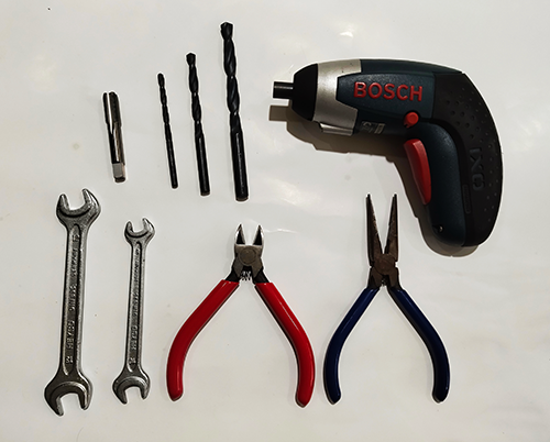
i-t-01

The picture is a suggested tool. Please choose the tool based on ease of use during construction.

  • 1/8 PT tooth tapping
  • 4、6、8 mm drill
  • 8、10、13 open wrench
  • Electric drill
  • Diagonal pliers
  • Needle nose pliers
  • Screwdriver

Cable ties, insulating tape, etc. are helpful for construction.
i-t-02

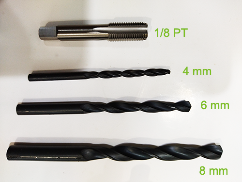
Pictured is the drilling tool for the connection of the pipe to the engine intake system.

In particular, the 1/8 PT tap drill bit is helpful for placing 6 mm pipe quick-connects.

Please choose the best tool according to the convenience of construction.

  • 1/8 PT tooth tapping
  • 4、6、8 mm drill

Silicone, sealant, etc., may aid in conduit construction if necessary.
Technology guide

i-01-00

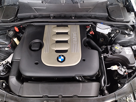
The illustration is an example, which must be considered in the arrangement of the location:
  • Keep away from hot equipment (exhaust pipes, turbo unit).
  • Pay attention to waterproof.
  • Does not affect regular maintenance work.
  • Easy to fix.
  • Distance between controller and reaction tank.
  • Easiest 12V power supply.
  • The optimum connection distance between the reaction tank pipe and the engine air intake system.
  • The controller must be installed in a position where it can clearly “sense engine vibration”, otherwise the system will not be able to start and function properly!

i-02-00

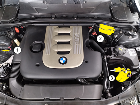
In the diagram, the yellow parts are:
  1. The power supply is taken from the direct power supply marked in red on the car.
  2. Controller
  3. Reaction tank

i-03-01

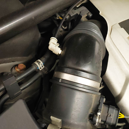
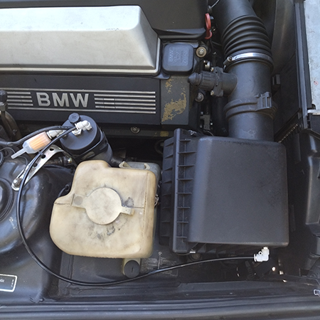
The photo is of the reaction tank piped to the engine「air filter housing」:

  • The selected air filter housing and the air duct straight line relative position.
  • Drill holes in the housing with an 8 mm bit and tap with a 1/8 PT tap.
  • Fit the 6 mm pipe quick connector of the system accessories.
  • Cut the 6mm tube to the appropriate length. Insert a small piece of 4mm heat shrink tubing on each end of the tube and connect it between the reaction tank and the air filter housing.
  • Appropriate fixation of the catheter if necessary.

Attention:

  1. Both ends of the conduit must be reduced in diameter.(i-04-00)
  2. The quick connector should be installed after the air filter to avoid any obstruction of the nanomolecules passing through the air filter.
  3. The position where the tubing connects to the air intake system is related to the system parameter settings.
  4. The first preferred way is to connect the hose to the air filter housing.

i-03-02

The photo is directly attached to the「Intake pipe」:

  • If you encounter a cylindrical air filter element, select an appropriate position to connect the conduit directly to the intake pipe (after the air filter).
  • Drill holes in the housing with an 8 mm bit and tap with a 1/8 PT tap.
  • Fit the 6 mm pipe quick connector of the system accessories.
  • Cut the 6 mm pipe to an appropriate length, insert a small section of 4 mm shrinking pipe at both ends of the pipe, and connect the reaction tank to the air filter housing.
  • Appropriate fixation of the catheter if necessary.

Attention:

  1. Both ends of the conduit must be reduced in diameter with shrink tubing.(i-04-00)
  2. The position where the pipe is connected to the intake system is related to the system parameter setting.
  3. Unless necessary, do not use this as a conduit connection method.
  4. The pipe connection position must be selected in the negative pressure area of the intake pipe, and cannot be selected in the pressurized area. (should be before the turbo)

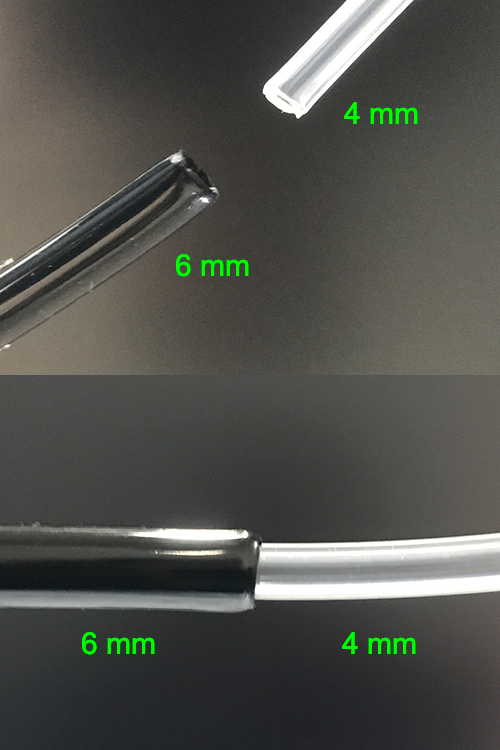
i-04-00

**Very important**

The photo shows the shrinking process of the 6 mm pipe:
  1. First, cut the 4 mm diameter transparent pipe in the installation fitting into 2 sections, each section is about 1 cm in length.
  2. Insert two 1 cm lengths of 4 mm diameter clear pipe into both sides of the 6 mm diameter black pipe.
  3. Leave the 4 mm clear pipe completely hidden and retract into the 6 mm black pipe.
  4. At this time, both ends of the 6 mm diameter catheter have a substantial inner diameter of only 2.5 mm.
Attention:
  • All engines, engines with a single cylinder displacement of less than 1000 cc, should undergo this duct reduction procedure.
  • Engines with a diesel displacement exceeding 6000 cc do not require this shrink tubing procedure.
  • If this step is skipped, excess nano-molecules may enter the engine, which may lead to inaccurate parameter definitions or increase fuel consumption.
  • Failure to do this step correctly will result in incorrect results.

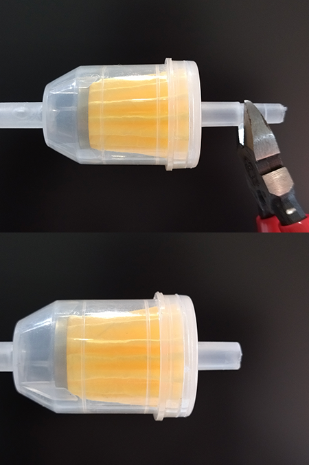
i-05-01

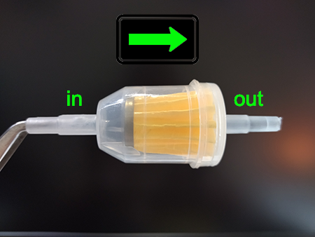
The picture shows the intake filter element of the reaction tank:

  1. Both ends can be air inlets, but it is still recommended to take the direction suggested by the photo, so that the degree of contamination of the filter element can be easily identified with the naked eye, so as to decide whether to replace it with a new one.
  2. The air inlet of the filter element is at the left ( in ) position.
  3. The right side ( out ) is inserted into the gas inlet of the reaction tank.

Attention:

  • Note the orientation of the filter element.

i-05-02

The picture is the modification process of the intake filter joint:
  1. The junction of the inlet filter element and the reaction tank must be cut off first to make it fit the 8 mm diameter quick connector of the reaction tank.
Attention:
  • Note the orientation of the filter element.
  • If the filter element cannot be tightly connected to the reaction tank for a specific reason, try wrapping the filter element joint with tape to thicken its pipe diameter.
  • Prevent the filter element from getting wet and blocking.

i-06-00

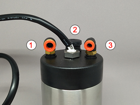
The picture is the reaction tank, and the numbers are marked as follows:

  1. Air inlet 8 mm diameter quick connector to connect air filter element.
  2. Catalyst fill port, lift off (OIL) lid to replenish catalyst.
  3. Air outlet 6 mm diameter quick connector for connecting conduit.

Attention:

  • The quick joints of the air inlet and the air outlet can be adjusted according to actual needs.
  • Do not disassemble the reaction tank, so as not to affect the warranty and abnormal function.

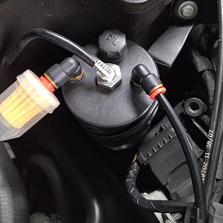
i-07-00

The picture is the actual application of the reaction tank:

  1. The air filter has been attached to the inlet end of the 8mm diameter fitting of the reaction tank.
  2. Catalyst filler OIL marking
  3. The 6 mm diameter fitting on the outlet end of the reaction tank is already tubed.

Attention:

  • The location where the reaction tank is installed should be as far away from the hot area of the engine as possible.
  • If the air filter is damp or dirty, it should be replaced with a new one.
  • The catalyst should not be added in excess, if the gas chamber in the reaction tank is submerged, it will not function properly.

i-07-01

The picture is the application status of the catalyst gauge of the reaction tank:

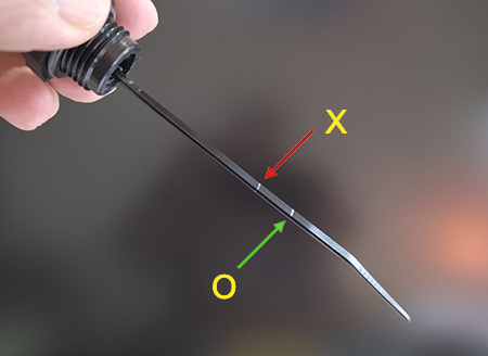
  1. The catalyst filler cap has a micro-scale with two horizontal lines on it.
  2. The reaction tank must have a certain space to reserve the vaporized nano-oxides. This space is approximately 5 cm below the catalyst filling port, as indicated by the red arrow in the figure. When adding, care should be taken not to exceed this line.
  3. The catalyst should be added carefully and in small amounts to the catalyst inlet, and avoid overfilling. The best position for adding the catalyst is indicated by the green arrow in the diagram.
  4. When the XThruster® app on the mobile phone indicates a low catalyst level, it should be refilled as soon as possible.

Attention:

  • Overfilling the reaction tank with catalyst can result in malfunction and cause the system to not function properly.

i-08-00

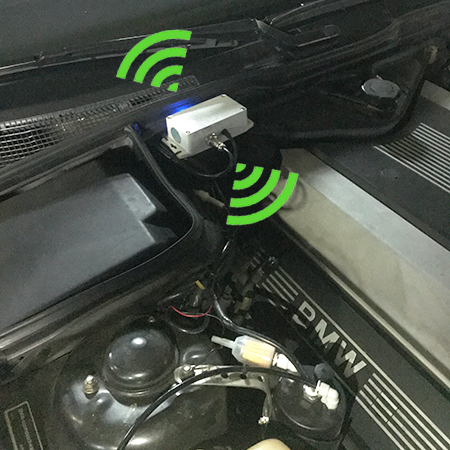
The picture is the actual situation of the controller installation:

  1. The selection of the controller should try to avoid water splashing and getting wet.
  2. Laying flat is the best arrangement.
  3. The Bluetooth antenna of the controller is directional (as shown in the figure), facing the cabin in a similar direction will help with Bluetooth communication with the phone.

Attention:

  • Placing a heat insulation film with a high metal content on the windshield can weaken the signal transmitted by the controller to the cabin.
  • The controller has a sensor inside, and if the engine is not started, the controller will only have power and Bluetooth lights, and it will be in sleep mode until the engine is started, and then the system will be activated.
  • If you need to test the system activation for some special reason, you can try to shake the controller body to wake up the system without starting the engine.